Editing Control Points
![]() To move, delete or add control points,
open or close paths, or
to convert segments from one form (line, gap, cubic Bézier) to
another, first select the
path, and then either click on the edit path icon or select
Edit->Path->Edit Path (Ctrl-I).
(Note that you should not have any other
objects selected.)
The path will then be displayed in draft format.
The currently selected control point and the
currently selected segment will appear in red. The other
control points will be orange.
To move, delete or add control points,
open or close paths, or
to convert segments from one form (line, gap, cubic Bézier) to
another, first select the
path, and then either click on the edit path icon or select
Edit->Path->Edit Path (Ctrl-I).
(Note that you should not have any other
objects selected.)
The path will then be displayed in draft format.
The currently selected control point and the
currently selected segment will appear in red. The other
control points will be orange.
A text-path object can have its underlying path edited in the same way as a normal path, but in edit mode you will also see the text (without anti-aliasing). Note that you can not edit a path if it belongs to a group; you must first ungroup it.
Use one of the following methods to select a control point:
- Click on the control point. (If two or more points coincide
with the location of the mouse, the point with the lowest
index will be selected.) Remember that if the
grid lock is on, mouse clicks will be translated to the
nearest tick mark, so even if the pointer is positioned over a
control point, the nearest tick mark may be outside the control
point bounds. If you want to use the
mouse to select and move a control point, make sure that you
first click to change the selection before initiating a drag or you
may move the wrong control.
- Press F6 or Shift-F6 until the required control point is selected. (You will need to use this method if two or more control points are in the same location and you don't want the one with the lowest index. You will also need to use this method if the grid lock is on and the control point's bounding box doesn't lie on a tick mark.)
Use one of the following methods to move a control point:
- Use the mouse to drag the point to its new location. (You can
initiate dragging outside of the selected control point, which
is useful if the grid lock is on or the controls are cluttered
together.)
- Use the edit path popup menu (F3) and select
Co-ordinates (F7). Enter the new
co-ordinates in the dialog box. (You
will need to use this method if the grid lock is on and
you want to move the point by an interval that is not a multiple of
the gap between tick marks.)
- Use the edit path popup menu and select Snap To Grid to move the control point to the nearest tick mark.
To exit edit mode deselect the edit path tool (Ctrl-I). If you have the Canvas click to exit option checked in the Graphics section of the Configure User Interface dialog, then you can also exit edit path mode by clicking the mouse on the canvas outside of any of the path's control points.
Whilst a path is in edit mode, you can use the edit path popup menu which provides functions to select or edit control points or the segments that they define. The following functions are available:
- Next Control (F6)
- Select the next control point. This is an alternative to using the
mouse to select the point.
- Previous Control (Shift-F6)
- Select the previous control point.
- Delete Point (Delete)
- Delete the currently selected control point. (This function is not
available for control points that govern the curvature of Bézier
segments, the controls on the line of symmetry for symmetric paths
or the pattern adjustment controls.) If the control point is the first or last
point in an open path it will delete the corresponding segment,
otherwise it will replace two adjacent segments with a single segment.
If the path is open and only has one segment, or if the path is
closed and has two segments, deleting a control point will delete
the path or the text-path object.8.1
- Add Point (Insert)
- Add a new control point in the middle of the currently selected
segment (thus replacing a single segment with two segments).
This will actually add three new points if the segment is a Bézier curve as it will also create the required curvature
control points.
- Convert To Line
- Convert a curve segment or a gap to a line segment.
- Convert To Curve
- Convert a line segment or a gap to a curve segment. The curvature
control points will be positioned so that the segment forms a
straight line. These can then be moved as required.
- Convert To Move
- Convert a line or curve segment to a gap.
- Path Symmetry
- This submenu can be used to add symmetry to the selected
shape. (See Symmetric Shapes for further details.)
- Continuity
If the selected segment is a Bézier curve this submenu provides functions that adjust the curvature control point to ensure that the gradient at the nearest join is continuous. This menu isn't available if it's not possible to do this (for example, if the nearest join is an end point).
There are two items in this submenu that are only enabled if the selected control point is a curvature control. The Equidistant function will move the control point so that it has the same gradient direction and magnitude as the gradient vector on the other side of the join. The Relative function will move the selected curvature control so that it has the same direction as the gradient on the other side of the join, but its magnitude will remain unchanged.
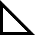
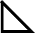
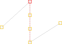
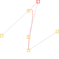
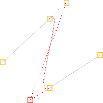
For example, in Figure 8.4 the path was originally an open line path with three line segments. The middle segment was selected and converted to a Bézier curve using the Convert To Curve function (Figure 8.4(a)). The Relative function was then used to change the starting gradient of the Bézier segment to make a smooth join between the first two segments (Figure 8.4(b)). The Bézier curve's third control point, which governs the end curvature, was selected, and the Relative function was again used to change the end gradient of the Bézier segment to make a smooth join between the last two segments (Figure 8.4(c)).
The toggle menu item Anchor is only available when a control point on the join between two Bézier curves has been selected. If this item is selected, when you adjust one of the adjacent curvature control points, the corresponding curvature control on the other segment will be adjusted to maintain continuity. An anchor image will appear in the control joining the two segments when this setting is on (as shown in Figure 8.5).
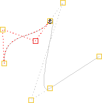
Figure 8.5: Continuity Anchor - Open Path Menu
- Open a closed path. There are two options available:
- Remove Last Segment
- Opens the path, removing the last segment (Figure 8.6(b)).
- Keep Last Segment
- Opens the path, but keeps the last segment (Figure 8.6(b)).

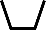
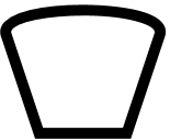
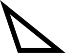
(a) (b) (c) Figure 8.6: Opening a path: (a) the original closed path; (b) the path in (a) was opened, removing the final segment; (c) the path in (a) was opened, keeping the last segment. - Close Path Menu
- Close an open path. There are three options available:
- Close With Line
- Close the path with a line between the last and first
control points of the original path (Figure 8.7(a)).
- Close With Curve
- Close the path with a Bézier curve between the last and first
control points such that the curve is continuous at the join
between the first and last segments of the original path (Figure 8.7(b)).
- Merge Ends
- Close the path, merging the last control point of the original
path with the first control point (Figure 8.7(c)).
(a) 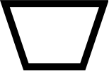
(b) (c) (d) Figure 8.7: Closing a path: (a) the original path; (b) the path in (a) was closed with a line; (c) the path in (a) was closed with a curve continuous at the join between adjacent segments; (d) the path in (a) was closed, merging the end points - Co-ordinates (F7)
- This menu item will display a dialog box in which you can
set the control point's x and
y values (instead of dragging the point to the required location).
Note that rounding errors may occur if the unit used in this dialog
doesn't have a convenient conversion factor with the storage unit.
- Snap To Grid (Ctrl+Shift-S)
- Move the currently selected control point to the nearest
tick mark.
- Break path
- Break the path into two separate
paths at the end of the currently
selected segment (not at the currently selected control point).
If the object is a text-path, the new text-paths will
both have the same text (that is, the text is not broken between
them).
See also:
- Reversing a Path's Direction
- Merging Paths
- Path Union
- Exclusive Or Function
- Path Intersection
- Path Subtraction
- Converting to a Path
- Line Colour
- Fill Colour
- Line Style
- Step-by-Step Example: Lettuce on Toast
- Step-by-Step Example: Bus
- Step-by-Step Example: A House With No Mouse
Footnotes
- ... object.8.1
- The text will also be lost when the text-path is deleted.