Symmetric Shapes
A shape can have symmetry added to it using the Path Symmetry submenu of the edit path popup menu described in the previous section.
![]() Take care with closed symmetric paths. Unexpected results
may occur, particularly if the path contains any gaps. This may
cause the stroked or filled shape to appear unsymmetric.
For example, Figure 8.8(a) shows the original
(non-symmetric path). This was then given a line of symmetry and
the path appears symmetric, as shown in Figure 8.8(b). In
Figure 8.8(c), two of the line segments have been
converted to gaps. The shape still appears symmetric although the
filled area has changed, but in Figure 8.8(d) the path
has been closed with a line so although the control points that
make up right side of the complete path are a reflection of the
original points on the left side, the shape no longer appears
symmetric.
Take care with closed symmetric paths. Unexpected results
may occur, particularly if the path contains any gaps. This may
cause the stroked or filled shape to appear unsymmetric.
For example, Figure 8.8(a) shows the original
(non-symmetric path). This was then given a line of symmetry and
the path appears symmetric, as shown in Figure 8.8(b). In
Figure 8.8(c), two of the line segments have been
converted to gaps. The shape still appears symmetric although the
filled area has changed, but in Figure 8.8(d) the path
has been closed with a line so although the control points that
make up right side of the complete path are a reflection of the
original points on the left side, the shape no longer appears
symmetric.
|


The Path Symmetry submenu provides the following functions:
- Has Symmetry
- If this menu item is selected, symmetry will be added to the path.
For example, Figure 8.9(a) shows a path in edit mode, and Figure 8.9(b) shows the
path with symmetry applied to it. There are now two extra
control points (coloured blue). These points govern the line
of symmetry8.2. In Figure 8.9(c), these two controls
have been moved.
If you later decide to remove the symmetry, deselect Has Symmetry.
 Adding symmetry to a closed shape may cause unexpected
results as the shape will be first opened (without removing the
last segment), the symmetry will be added, and then the symmetric
shape will be closed, merging the end points.
Adding symmetry to a closed shape may cause unexpected
results as the shape will be first opened (without removing the
last segment), the symmetry will be added, and then the symmetric
shape will be closed, merging the end points.
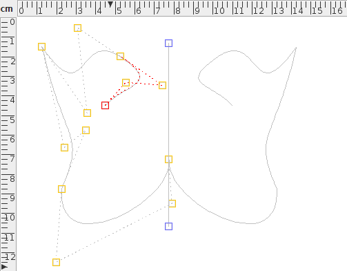
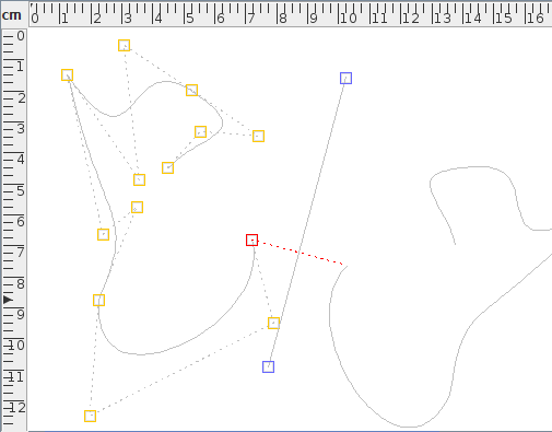
- Anchor Join
- When you add symmetry to a path, the final control point of the
underlying path is anchored to the line of symmetry. That is, it
can only move along the line defined by the two blue
control points. To remove the constraint, deselect this menu
item. In Figure 8.9(d), the
Anchor Join item was
deselected, and the end control was then moved away from the line of
symmetry.
Note that this function places a gap (move) segment between the end control and its symmetric counterpart, which will produce an unsymmetric effect if the path is then closed. This gap can be changed to a line or curve, using Convert To Line or Convert To Curve, as described in Editing Control Points. In Figure 8.9(e), the join has been changed to a curve. Unlike the Bézier curves in the non-symmetric paths, this curve only has one curvature control.
- Anchor Start Control
- This menu item is only available for closed symmetric paths.
If you close a symmetric path using the
Merge Ends function, the first
control point of the underlying path will be
anchored to the line of symmetry. The
Anchor Start Control menu item
will remove this constraint.
For example, Figure 8.10(a) shows a closed symmetric path (a closed version of Figure 8.9(e)). The anchor constraint on the first control was then removed and the control was moved to the left (Figure 8.10(b)). As with the join segment (above) the closing segment between the start control and its reflection can be changed to a curve with one curvature control (Figure 8.10(c)).


|


See also:
Footnotes
- ... symmetry8.2
- The line of symmetry extends infinitely though the two controls, but only the part of the line between the two points is actually displayed in edit mode.