JDR/AJR File Formats
FlowframTk has two native file formats that it can both read and write. The JDR (.jdr) format is binary written in the big-endian fashion. The AJR (.ajr) format is an ASCII format. The AJR format has less precision than the JDR format. The current version number for both formats is 1.9.
The first line of the ASCII AJR format must be:
AJR 1.8The version number must be followed by white space (such as a newline or space character).
The binary JDR format starts with a sequence of the three 16-bit Unicode characters "JDR" followed by the version string (not a decimal number) which is save as an integer (the string length) followed by each character of the version string. In Java this is implemented using:
dout.writeChars("JDR");
dout.writeInt(version.length());
dout.writeChars(version);
where dout is a java.io.DataOutputStream object
and version is a java.lang.String.
The remainder of both the JDR and AJR formats have the same syntax but the data types are stored differently.
- integer
- The binary version writes 32-bit signed two's complement integers using the
writeInt(int) method of the
java.io.DataOutputStream class. The ASCII version writes
the integer to the file followed by white space.
- byte
- The binary version writes 8-bit signed two's complement bytes using the
writeByte(byte) method of the
java.io.DataOutputStream class. The ASCII version is the
same as for the integer type, but the range of values is more
limited.
- long
- The binary version writes 64-bit two's complement integers using the
writeLong(long) method of the
java.io.DataOutputStream class. The ASCII version is the
same as for the integer type.
- float
- The binary version writes single-precision 32-bit floating point
values using the writeFloat(float) method of the
java.io.DataOutputStream class. The ASCII version writes
the number (possibly truncated) to the file followed by white space.
- double
- The binary version writes double-precision 64-bit floating point
values using the writeDouble(double) method of the
java.io.DataOutputStream class. The ASCII version is the
same as for the float type.
- boolean
- The binary version writes boolean values using the
writeBoolean(boolean) method of the
java.io.DataOutputStream class. The ASCII version writes
the number 0 (false) or 1 (true) to the file
followed by white space.
- char
- The binary version writes a single 16-bit Unicode character using
the writeChar(int) method of the
java.io.DataOutputStream class. The ASCII version writes
the character followed by white space.
- string
- A string consisting of <n> 16-bit Unicode characters is written
as an integer followed by the <n> characters of type
char. For the binary format, this is equivalent to:
dout.writeInt(text.length());
dout.writeChars(text);
where dout is a java.io.DataOutputStream object and text is a java.lang.String. For the ASCII format, the length is written as an integer followed by a single white space character. (Avoid using println for just <n> as the end-of-line character for some operating systems consists of two characters.) Then the string is written followed by white space. For example:out.print(String.format("%d %s ", text.length(), text));orout.println(String.format("%d %s", text.length(), text));(where out is a java.io.PrintWriter object.) As in the above example, a newline character can be used after the string, just not after the number.A null or empty string is just written as the number 0. For example, for the binary version:
dout.writeInt(0);
or for the ASCII version:out.print("0 "); - transform-matrix
- A transformation matrix is saved as six double values
representing the scale-x factor, the shear-y
factor, the shear-x factor, the scale-y
factor, the x-translation and the
y-translation. For versions below 1.8, the translations
are in terms of the bp PostScript unit, otherwise they are in
terms of the storage unit.
- float-array
- An array of float values is stored as an integer
<n> indicating the length of the array (may be 0 for a null or empty
array) followed by the <n> float array elements.
- double-array
- An array of double values is stored as an integer
<n> indicating the length of the array (may be 0 for a null or empty
array) followed by the <n> double array elements.
- unit-id
- A unit identifier is stored as a byte. This may take one of eight
values: 0 (pt), 1 (inch), 2 (cm), 3 (bp), 4 (mm), 5
(pc), 6 (dd) or 7 (cc).
- length
- Lengths that are independent of the storage unit are stored as a
double followed by the unit-id.
- angle
- An angle is stored as a double followed by a byte
indicating the unit where 0 represents radians and 1 represents
degrees.
- paint
- Colour data is stored as a char indicating the
colour type (<col-id>). Available types are listed in
Table A.1.
If <col-id> is T (transparent) this ends the paint information. Otherwise <col-id> is followed by the colour specifications (<colour-specs>).
- rgb
- RGB colour specs are saved as four float values in the
range 0 to 1 (inclusive) representing the red, green, blue and alpha
components.
- cymk
- CYMK colour specs are saved as five float values in the
range 0 to 1 (inclusive) representing the cyan, magenta, yellow, black
and alpha components.
- hsb
- HSB colour specs are saved as four float values
representing the hue, saturation, brightness and alpha components.
The hue value must lie in the range 0 (inclusive) to 360
(exclusive). The other values must lie in the range 0 to 1
(inclusive).
- grey
- Grey specs are saved as two float values in the range 0 to
1 (inclusive) representing the grey and alpha components.
- linear-paint
- Linear gradient paint specs are saved as the start paint, the
end paint followed by an integer indicating the
direction, which may be one of: 0 (North), 1 (North-East), 2 (East),
3 (South-East), 4 (South), 5 (South-West), 6 (West) or 7 (North-West).
FlowframTk doesn't support another gradient type as the
start or end paint.
- radial-paint
- Radial gradient paint specs are saved as the start paint, the
end paint followed by an integer indicating the
starting location, which may be one of: 0 (North), 1 (North-East), 2 (East),
3 (South-East), 4 (South), 5 (South-West), 6 (West), 7 (North-West)
or 8 (Centre).
FlowframTk doesn't support another gradient type as the
start or end paint.
Spaces in any syntax specifications below are for clarity and ease of line breaking only and don't form part of the specification (although white space may be acceptable at that point in the ASCII AJR format, according to the above data types).
-
Regardless of whether or not the settings are saved in the file, as from JDR/AJR version 1.8 the storage unit <storage-id> is always present immediately after the version number and is used for all lengths described below (including co-ordinates) unless otherwise indicated. The unit is saved as a unit-id type, as described above.JDR1.8 onwards

JDR1.8 onwards Versions below 1.8 must have all lengths stored as PostScript points.
-

Next is a value <settings-id> indicating whether or not the FlowframTk settings are stored. In version 1.3 onwards, this value is a byte, and may take one of three values: 0 (no settings), 1 (all settings) or 2 (paper size only). In versions prior to 1.3, this value is a boolean value, where true indicates all settings and false indicates no settings. - The settings information is stored as follows when the
<settings-id> is 1:
JDR1.0-1.7

JDR1.0-1.7
If <settings-id> is 2, just <paper> is present.JDR1.8 onwards <show-grid> <lock-grid> <show-rulers> <tool-id> <paper> <grid> <point size> <scale flag> JDR1.8 onwards - <show-grid> is a boolean variable indicating whether or
not to display the grid.
- <lock-grid> is a boolean variable indicating whether or
not to lock the grid.
- <show-rulers> is a boolean variable indicating whether
or not to show the rulers.
- <tool-id> is an integer indicating which tool to select. For
versions below 1.8, this must be an integer in the range 0 and 7
(inclusive). As from version 1.8, this must be in the range 0 and 8
(inclusive). Table A.2 indicates the ID for each tool.
-
JDR1.0-1.7 For versions below 1.8, <normalsize> is an integer indicating the LaTeX normal font size. As from version 1.8, this value is stored later (see below) and isn't governed by the settings flag. JDR1.0-1.7 - The <paper> specs are:
JDR1.0-1.2
![\begin{syntax}
\meta{paper-id} [\meta{width} \meta{height} \meta{portrait-flag}]
\end{syntax}](img7.png)
JDR1.0-1.2
The paper size <paper-id> is specified as a byte. For versions below 1.3, this must be a number in the range 0 to 18 (inclusive), otherwise it must be in the range 0 to 72 (inclusive). Table A.3 indicates the ID for each paper size, and Table A.4 shows additional values for version 1.3 onwards. If the paper size has an ID of 18 (user defined), then there must follow the paper <width> (a double in bp) and <height> (a double in bp). For versions prior to 1.3, the user defined setting must also be followed by <portrait-flag> a boolean variable to indicate whether or not the orientation is portrait (true) or landscape (false). The paper dimensions are always stored in PostScript points (bp) and the unit id isn't saved. (This is still true for version 1.8.)JDR1.3 onwards
![\begin{syntax}
\meta{paper-id} [\meta{width} \meta{height}]
\end{syntax}](img8.png)
JDR1.3 onwards Table A.3: Paper Size Identifiers ID Paper Size ID Paper Size 0 A0 (portrait) 9 A0 (landscape) 1 A1 (portrait) 10 A1 (landscape) 2 A2 (portrait) 11 A2 (landscape) 3 A3 (portrait) 12 A3 (landscape) 4 A4 (portrait) 13 A4 (landscape) 5 A5 (portrait) 14 A5 (landscape) 6 letter (portrait) 15 letter (landscape) 7 legal (portrait) 16 legal (landscape) 8 executive (portrait) 17 executive (landscape) 18 user defined
Table A.4: Additional Paper Size Identifiers (JDR v1.3 onwards) ID Paper Size ID Paper Size 19 A6 (portrait) 46 A6 (landscape) 20 A7 (portrait) 47 A7 (landscape) 21 A8 (portrait) 48 A8 (landscape) 22 A9 (portrait) 49 A9 (landscape) 23 A10 (portrait) 50 A10 (landscape) 24 B0 (portrait) 51 B0 (landscape) 25 B1 (portrait) 52 B1 (landscape) 26 B2 (portrait) 53 B2 (landscape) 27 B3 (portrait) 54 B3 (landscape) 28 B4 (portrait) 55 B4 (landscape) 29 B5 (portrait) 56 B5 (landscape) 30 B6 (portrait) 57 B6 (landscape) 31 B7 (portrait) 58 B7 (landscape) 32 B8 (portrait) 59 B8 (landscape) 33 B9 (portrait) 60 B9 (landscape) 34 B10 (portrait) 61 B10 (landscape) 35 C0 (portrait) 62 C0 (landscape) 36 C1 (portrait) 63 C1 (landscape) 37 C2 (portrait) 64 C2 (landscape) 38 C3 (portrait) 65 C3 (landscape) 39 C4 (portrait) 66 C4 (landscape) 40 C5 (portrait) 67 C5 (landscape) 41 C6 (portrait) 68 C6 (landscape) 42 C7 (portrait) 69 C7 (landscape) 43 C8 (portrait) 70 C8 (landscape) 44 C9 (portrait) 71 C9 (landscape) 45 C10 (portrait) 72 C10 (landscape)
- The <grid style> has the syntax:
JDR1.0-1.5
where:- <unit> is the unit-id used for the rulers
and grid. (Restricted to: 0 (TeX pt), 1 (inches),
2 (centimetres) or 3 (PostScript points).)
- <major> and <minor> are integers representing the major grid divisions and the subdivisions, respectively.
JDR1.0-1.5 JDR1.6 onwards
The <grid-id> is a byte representing the grid style ID. This may be:- 0
- A rectangular grid. The <grid-specs> are:
where - 1
- A radial grid. The <grid-specs> are:

where: - 2
- An isometric grid (Version 1.8 onwards.) The <grid-specs> are:
where - 3
- A Tschichold grid (Version 1.8 onwards.) The <grid-specs> are the same as for the rectangular grid.
JDR1.6 onwards - <unit> is the unit-id used for the rulers
and grid. (Restricted to: 0 (TeX pt), 1 (inches),
2 (centimetres) or 3 (PostScript points).)
-
JDR1.8 onwards
As from JDR version 1.8, the <point size> is also saved as a length, followed by a boolean value <scale flag> indicating whether the control point scaling is enabled.JDR1.8 onwards
- <show-grid> is a boolean variable indicating whether or
not to display the grid.
-
JDR1.9 onwards

JDR1.9 onwards JDR1.8

For version 1.8 onwards, the LaTeX normal size value is always saved at this point, regardless of the <settings-id>. In addition, from version 1.8, preamble text, document class and absolute pages setting are now saved. Version 1.8 only stores the early-preamble text. As from version 1.9, the mid-preamble and end-preamble text is also stored.- The normal size value <normalsize> is stored as an integer.
- The preamble text <preamble> is stored as a string
and may be empty or null. Similarly for the <mid-preamble>
and <end-preamble> for version 1.9 onwards.
- If the default document class setting is enabled, <class
name> is saved as an empty or null string otherwise the user
specified <class name> is saved.
- The <absolute pages flag> is saved as a boolean value, where true indicates flowfram's pages=absolute option and false indicates flowfram's pages=relative option.
JDR1.8 - The normal size value <normalsize> is stored as an integer.
- The objects that constitute the
image are now stored. When saving to a file, an outer grouping is
implied that is not evident whilst using FlowframTk. This means that
there should always be a single group structure saved to file which
contains all the objects that
constitute the picture. Each object is then recursively
stored. For example, if an image contains a path, a
group and a text area, in the
JDR/AJR file these three objects will be stored as a single
group structure containing the three objects. If in FlowframTk you
explicitly group all the objects, then in the
JDR file, the outermost implicit group will contain
only one object which will be this group. It's an error
for the top-level object to be anything other than a group.
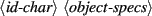
Each object has the following format:
![\begin{syntax}
\begin{jdrversion}{1.0 \& 1.1}
\meta{id-char} \meta{object-specs}...
...{fflag} [\meta{flowframe-specs}]
\meta{description}
\end{jdrversion}\end{syntax}](img15.png)
where <id-char> is a char determining the object type:JDR1.0-1.4 JDR1.0-1.4 JDR1.5 As versions 1.0-1.4. Additionally: JDR1.5 JDR1.6 onwards As version 1.5. Additionally: JDR1.6 onwards The object specifications <object-specs> vary according to the object type and are described below. <fflag> is a boolean value indicating whether or not this object has flowframe data associated with it. If true, then the flowframe specifications <flowframe-specs> should follow (see below), otherwise <flowframe-specs> should be omitted. Note that JDR version 1.2 and above contains the string <description>, which was omitted in earlier versions.
Recall from above that the image is stored with an implied outer grouping. The <flowframe-specs> for this implicit group represents the image typeblock and the <description> represents the image description.
The <object-specs> are as follows:
- Group data, G, is stored as:
where <n> is an integer indicating the number of objects within the group. There should then follow <n> lots of <object data>, where <object data> is the data for each object within the group, and is as described above. - Path data, P, is stored as
follows:
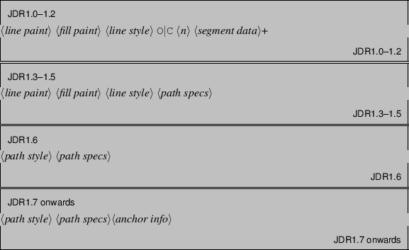
where <line paint> and <fill paint> are paint specifications and <line style> is the line style data (see below).The <path specs> are

where the char value O or C indicates whether the path is open (O) or closed (C), <n> is an integer indicating the number of segments that constitute the path. This should be followed by <n> lots of <segment data> (described below).Version 1.3 removed the redundancy present in earlier versions but requires that the starting point <start point> follows the number of segments (<n>). The starting point is stored as two double numbers. For versions below 1.8, these values are always in terms of the PostScript point bp. As from version 1.8, they are in terms of the storage unit, as described above.
Version 1.7 added anchor information (<anchor info>). This comes after the above path specifications. Control points are indexed from 0 and include curvature control points. For example, a path that consists of a line segment followed by a Bézier segment has 5 control points: index 0 is the point at the start of the path (the start of the line segment), index 1 is the point at the join between the line segment and Bézier segment, indices 2 and 3 are the two curvature control points and index 4 is the end point. The anchor information is the list of integer indices for which the anchor is on. This list must be in ascending order of index and is terminated by -1. Only control points occuring between a continuous join may be anchored.
For example, in the ASCII AJR version
3 6 9 -1
indicates that control points 3, 6 and 9 have the anchor setting on. If no controls are anchored, the -1 is still required.- Version 1.6 onwards stores the <path style>
specification as

where <id> is a byte indicating the path style. This may be 0 (basic stroke) or 1 (text-path stroke).- The basic stroke <specs> are:

where <line style> is described below. - The text-path stroke <specs> are:

where <text-path style> is described below.A path should only have a text-path stroke if it is the base path for a composite shape.
- The basic stroke <specs> are:
- The <line style> data has changed from file version 1.0 to 1.1 to
take into account the inclusion of mid point markers,
and is stored as follows:
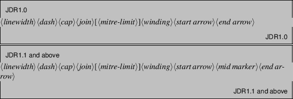
where:- <linewidth> the line width stored as a float
(below version 1.8) in PostScript points (bp). For version
1.8 onwards, the line width is stored as a length.
- <dash> is the dash pattern. This is stored as
a float-array, optionally followed by the float offset.
The array may be empty or null to indicate a solid line, otherwise
it should have an even number of elements representing
<dash><gap> pairs. The offset is only saved for a
non-empty, non-null array.
The unit of measurement (not saved in the dash pattern specs) is bp for versions below 1.8 and the storage unit for version 1.8 onwards.
- <cap> is the cap style, stored as a byte. It may
only have one of the following values: 0 (butt), 1 (round) or 2
(square).
- <join> is the join style, stored as a byte.
It may only have one of the following values: 0 (mitre), 1 (round)
or 2 (bevel).
- <mitre-limit> is the mitre-limit
and should only be stored if the join style is a mitre. For versions
below 1.8, the mitre-limit is stored as a float, otherwise
it's stored as a length.
- <winding> is the winding rule, stored as a byte.
It may only have one of the following values: 0 (Even-Odd) or
1 (Non Zero).
- <start arrow> and <end arrow> are the starting and
ending arrow styles. The <mid marker> is the style for the
mid-point markers. Each marker type (start/mid/end) has the same
format, but the file format varies as follows:
JDR1.0
![\begin{syntax}
\meta{id}[\meta{size}\meta{is double}\meta{is reversed}]
\end{syntax}](img23.png)
where <id> is a byte identifying the arrow type. This may be one of: 0 (none), 1 (pointed), 2 (triangle), 3 (circle), 4 (diamond), 5 (square), 6 (bar) or 7 (single). <size> is float representing the arrow size. (Some arrows only have a fixed size, but a size must still be present.) <is double> is a boolean value indicating whether the arrow head is a double arrow (<true>) or a single arrow (<false>). <is reversed> is a boolean value indicating whether the arrow head has been reversed. The values <size><is double><is reversed> are omitted if <id> equals 0 (no arrow head).JDR1.0 JDR1.1-1.3
![\begin{syntax}
\meta{id}[\meta{marker data}]
\end{syntax}](img24.png)
where <id> is a byte identifying the marker type. If <id> is 0, then <marker data> should be omitted, otherwise it should be present. Valid <id> values are listed in Table A.5.The <marker data> is stored as follows:

where:- <size> is a float representing the marker size
(some markers will ignore this attribute, but it must still be
present in the file.)
- <repeat> is a byte identifying the repeat factor
(a value of 1 indicates a single marker, a value of 2 indicates
a double marker, a value of 3 indicates a triple marker.)
- <is reversed> is a boolean value indicating whether
or not the marker has been reversed.
- <orient data> is the marker orientation data. This has
the form <auto-orient>[<angle>] where <auto-orient>
is a boolean value indicating whether the marker should be
oriented along the path. If <auto-orient> is true, <angle>
should be omitted, otherwise <angle> should be a float
representing the orientation angle (in Radians).
- <colour data> is the marker paint where
a transparent value indicates the colour should be derived from
the path to which the marker is attached, and there is no provision
for gradient paint markers.
- <overlay> is a boolean value indicating whether
to overlay composite markers.
- <composite data> is the data for composite markers. This has the same format as the <marker data>. If the <composite data> has a marker id of 0, then the marker is not a composite marker. Although the format allows for nested composite markers, FlowframTk's marker settings dialog boxes do not allow for it.
Table A.5: Marker IDs 0 No marker 11 Box Filled 1 Pointed 12 Box Open 2 Triangle 13 Cross 3 Circle 14 Plus 4 Diamond 15 Star 5 Square bracket 16 Triangle Up Filled 6 Bar 17 Triangle Up Open 7 Single 18 Triangle Down Filled 8 Round bracket 19 Triangle Down Open 9 Dot Filled 20 Rhombus Filled 10 Dot Open 21 Rhombus Open
JDR1.1-1.3 JDR1.4 onwards Table A.6: Additional Marker IDs (JDR 1.4) 22 Pentagon Filled 41 Half Cusp Down 60 Open Semicircle 23 Pentagon Open 42 Alt Single 61 Filled Semicircle 24 Hexagon Filled 43 Alt Single Open 62 Open 5 Pointed star 25 Hexagon Open 44 Triangle Open 63 Filled 5 Pointed star 26 Octagon Filled 45 Circle Open 64 Asterisk 27 Octagon Open 46 Diamond Open 65 Scissors Down Filled 28 Pointed 60 47 Brace 66 Scissors Up Filled 29 Pointed 45 48 Rectangle Cap 67 Scissors Down Open 30 Hooks 49 Chevron Cap 68 Scissors Up Open 31 Hook up 50 Fast Cap 69 Heart Right Filled 32 Hook Down 51 Round Cap 70 Heart Right Open 33 Half Pointed Up 52 Triangle Cap 71 Heart Filled 34 Half Pointed Down 53 Inverted Triangle Cap 72 Heart Open 35 Half Pointed 60 Up 54 Inverted Chevron Cap 73 Snowflake 36 Half Pointed 60 Down 55 Inverted Fast Cap 74 Star Chevron Open 37 Half Pointed 45 Up 56 Alt Bar 75 Star Chevron Filled 38 Half Pointed 45 Down 57 Alt Round 76 Star 6 Filled 39 Cusp 58 Alt Square 77 Star 6 Open 40 Half Cusp Up 59 Alt Brace 78 Equilateral Filled 79 Equilateral Open
For version 1.4 onwards the markers are stored as
where <id> is a byte identifying the marker type. If <id> is 0, then <marker data> should be omitted, otherwise it should be present. Valid <id> values are listed in Table A.5 and Table A.6. Additional markers listed in Table A.7 are also available for version 1.6 onwards.The <marker data> is stored as follows:
![\begin{syntax}
\meta{size} \meta{repeat} \meta{is reversed} \meta{orient data}
...
...epeat offset flag} [\meta{repeat offset}]]
\meta{composite data}
\end{syntax}](img26.png)
(spaces for syntax clarity) where: <user offset flag> [<user offset>] <repeat offset flag> [<repeat offset>] are only specified if the <overlay> is false. Additionally, <user offset> and <repeat offset> are only specified if <user offset flag> or <repeat offset flag> are true, respectively.- <size> is a float (bp unit implied) for
versions below 1.8 and is a length for version 1.8 onwards.
- <repeat> is a byte identifying the repeat factor
(a value of 1 indicates a single marker, a value of 2 indicates
a double marker, a value of 3 indicates a triple marker.)
- <is reversed> is a boolean value indicating whether
or not the marker has been reversed.
- <orient data> is the marker orientation data. This is as
for versions 1.1-1.3 except that for version 1.8 onwards the
orientation <angle> (if required) is stored as an angle.
- <colour data> is the marker paint is as for
versions 1.1-1.3.
- <overlay> is a boolean value indicating whether
to overlay composite markers.
If the <overlay> is false:
- <user offset flag> is a boolean value indicating
whether the marker offset is specified by the user (true) or
determined automatically (false).
- <user offset> indicates the marker
offset from the vertex. For versions below 1.8 this is stored as a
float (bp unit implied) otherwise it's stored as a length. This is only
present if <user offset flag> is true.
- <repeat offset flag> is a boolean indicating whether the
repeat offset (i.e. gap between repeat markers) is specified by
the user (true) or determined automatically (false).
- <repeat offset> indicates the gap between repeat markers. For versions below 1.8 this is stored as a float (bp unit implied) otherwise it's stored as a length. This is only present if <repeat offset flag> is true.
- <user offset flag> is a boolean value indicating
whether the marker offset is specified by the user (true) or
determined automatically (false).
- <composite data> is the data for composite markers. This has the same format as the <marker data>. If the <composite data> has a marker id of 0, then the marker is not a composite marker. Although the format allows for nested composite markers, FlowframTk's marker settings dialog boxes do not allow for it.
JDR1.4 onwards - <size> is a float representing the marker size
(some markers will ignore this attribute, but it must still be
present in the file.)
- <linewidth> the line width stored as a float
(below version 1.8) in PostScript points (bp). For version
1.8 onwards, the line width is stored as a length.
- Each path segment <segment data> is stored as:
where <id> is a char representing the segment type. This can be one of: B (cubic Bézier), L (line) or M (move). For versions below 1.8, the co-ordinates are always bp. As from version 1.8, the co-ordinate unit is as specified by the storage unit described above.- Bézier segments are stored as follows:
JDR1.0-1.2 <c0x> <c0y> <c1x> <c1y> <c2x> <c2y> <c3x> <c3y> JDR1.0-1.2
where <c0x> and <c0y> are the x and y co-ordinates of the starting point, <c1x> and <c1y> are the x and y co-ordinates of the first curvature control point, <c2x> and <c2y> are the x and y co-ordinates of the second curvature control point, and <c3x> and <c3y> are the x and y co-ordinates of the end point. Each value is stored as a double. The unit of measurement is bp for versions below 1.8, otherwise it's the storage unit as described above.JDR1.3 onwards <c1x> <c1y> <c2x> <c2y> <c3x> <c3y> JDR1.3 onwards - Line and move to (gap) segments are stored as follows:
JDR1.0-1.2 <x0> <y0> <x1> <y1> JDR1.0-1.2
where <x0> and <y0> are the x and y co-ordinates of the starting point and <x1> and <y1> are the x and y co-ordinates of the end point. Each value is stored as a double. The unit of measurement is bp for versions below 1.8, otherwise it's the storage unit as described above.JDR1.3 onwards <x1> <y1> JDR1.3 onwards
- Bézier segments are stored as follows:
- Version 1.6 onwards stores the <path style>
specification as
- Text area (T) data is stored as follows:
JDR1.0-1.7
![\begin{syntax}
\meta{font-specs} \meta{transform}
\meta{latex-flag} [\meta{latex-specs}] \meta{text paint} \meta{text}
\end{syntax}](img27.png)
JDR1.0-1.7 JDR1.8 onwards <outline-flag> [<fill paint>] <font-specs> <transform> <latex-flag> [<latex-specs>] <text paint> <text> JDR1.8 onwards - <outline-flag> is a boolean
value that indicates whether or not the text should be rendered as
an outline. If true, <fill paint> follows, which is the
paint used to fill the interior. A transparent paint
indicates the interior shouldn't be filled.
- <font-specs> has the syntax:

The <family> must be a non-empty, non-null string indicating the name of the font (as used by FlowframTk, not when exported to a LaTeX file, so it's a system font rather than a TeX font).The <shape> is a byte indicating the font shape (0 for upright, 1 for emphasized, 2 for italic, 3 for slanted and 4 for smallcaps). Version 1.6 and below only permitted 0 or 1 for the shape. Although the file format allows five different shape styles, java.awt.Font only supports plain or italic, so when rendering on the canvas, FlowframTk treats emphasized, italic and slanted as Font.ITALIC and the other styles as Font.PLAIN. The Italic option in the font style dialogs actually sets the shape to type 1 (emphasized) rather than type 2.
The <weight> is a byte indicating the font weight (0 for medium, 1 for bold).
For versions below 1.8 the font size is a non-negative integer, otherwise it's stored as a non-negative length.
- <transform> is a transform-matrix indicating the
text transformation relative to the top left corner of the
canvas.
- The <latex-flag> is a boolean value that indicates
whether the LaTeX-related attributes (<latex specs>) are saved.
If true, the syntax for <latex specs> is
JDRbelow 1.8

JDRbelow 1.8
The <latex font specs> are the LaTeX font declarations: <family>, <weight>, <shape> and <size>. Each attribute is stored as a string.JDR1.8 onwards

JDR1.8 onwards The <h-align> element represents the horizontal alignment and is stored as a byte that may be one of: 0 (left), 1 (centre) or 2 (right).
The <v-align> element represents the vertical alignment and is stored as a byte that may be one of: 0 (top), 1 (middle), 2 (baseline) or 3 (bottom).
The LaTeX alternative text <latex text> is a string. If empty or null, the LaTeX alternative text should be considered equivalent to <text>.
- <outline-flag> is a boolean
value that indicates whether or not the text should be rendered as
an outline. If true, <fill paint> follows, which is the
paint used to fill the interior. A transparent paint
indicates the interior shouldn't be filled.
- Bitmap (I) information is stored as follows:
![\begin{syntax}
\meta{filename} \meta{latex-flag} [\meta{latex-bitmap-specs}]
\meta{transformation}
\end{syntax}](img31.png)
where:- <filename> is a non-empty, non-null string
containing the file name. This may be a path relative to the JDR/AJR
file for version 1.8 onwards.
- If the boolean value <latex-flag> is true, it must
be followed by <latex-bitmap-specs>
- <latex-bitmaps-specs> has the following format:

where <lfilename> is a string containing the LaTeX pathname for the bitmap. A null or empty value indicates it should be determined from <filename> (replacing the pathname separator with / if necessary). The image command is stored in the string <imgcmd> and may be empty or null. - <transformation> is a transform-matrix. The origin is the bottom left corner of the bitmap.
- <filename> is a non-empty, non-null string
containing the file name. This may be a path relative to the JDR/AJR
file for version 1.8 onwards.
- Composite Shapes
As from version 1.6, all composite shapes except symmetric shape (X, R, C and L) have <object-specs> in the form:

For symmetric shapes (S) the syntax is:

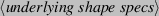
The <underlying shape specs> is the specification for the underlying shape in the form:
where <id-char> is as above, but limited to the shape IDs, so the text (T), bitmap (B) and group (G) IDs aren't permitted here.The underlying shape may be another composite shape. Descendent underlying shapes refer to the composite shape's underlying shape and any descendent of that underlying shape if it is also a composite shape. The base underlying shape is the maximal descendent underlying shape and must be a path (P), in which case <id-char> <object-specs> will be P<path style><path specs><anchor info> (<anchor info> is omitted below version 1.7).
Although the descendent underlying shapes may be another composite shape, they can't share the same type as either their ancestor or desendent shapes. For example, a text-path may have a pattern as its underlying shape, but a pattern can't have another pattern as its underlying shape.
The <modifier specs> are as follows:
- Text-paths (X) are not available for versions below 1.5.
For this type of composite shape, the <modifier specs> are only present from version 1.8 and relate to the outline option <outline-flag> [<fill paint>], which is the same as for text-areas. So the <object-specs> are:
JDR1.8 onwards
![\begin{syntax}
\meta{outline-flag} [\meta{fill paint}] \meta{underlying shape specs}
\end{syntax}](img36.png)
JDR1.8 onwards JDR1.6-1.7
JDR1.6-1.7 For version 1.5 the <object-specs> are:
JDR1.5

For version 1.5, the <line style> and <path specs> are as described earlier. The base path must have the text-path stroke (id 1) <path style>.JDR1.5 - The <text-path style> is
stored as:
![\begin{syntax}
\meta{font specs} \meta{transform} \meta{latex-flag}
[\meta{latex specs}] \meta{text}
\end{syntax}](img39.png)
where:- <font specs> are the same as for
text areas.
- <transform> is a transform-matrix indicating the
text transformation relative to the underlying shape (see
Combining a Text Area and Path to Form a Text-Path).
- The <latex-flag> is a boolean value that indicates
whether the LaTeX-related attributes (<latex specs>) are saved.
If true, the syntax for <latex specs> is
JDRbelow 1.8
JDRbelow 1.8
This is the same as for text areas but additionaly includes the delimiters used by the pgf package's text decoration function for version 1.8 onwards. These are both stored as a char.JDR1.8 onwards
JDR1.8 onwards
- <font specs> are the same as for
text areas.
- The <text> is stored as a string and shouldn't be empty or null.
- The <text-path style> is
stored as:
- Symmetric shapes (S) are not available for versions
below 1.6. For newer versions, the <modifier specs> are:
![\begin{syntax}
\meta{join anchored} [\meta{join segment}]
\meta{symmetry x0} \...
...1}
\meta{closed} [\meta{close anchored} [\meta{closing segment}]]
\end{syntax}](img40.png)
where:- The boolean value <join anchored> indicates
whether or not the join between the original shape and its
reflection is anchored.
- If the join isn't anchored, <join segment> is the
information about the joining segment. This is omitted if
<join anchored> is true. The syntax for the join segment is:
![\begin{syntax}
\meta{segment-id} [\meta{segment specs}]
\end{syntax}](img41.png)
where the <segment-id> is a char indicating the segment type. This may be one of m (gap), l (line) or c (Bézier curve).- The <segment specs> for both the gap (m) and
line (l) segments is omitted.
- The <segment specs> for the Bézier curve is:

where <cx> and <cy> are the x- and y-coordinates of the curvature control, respectively, and are each stored as a double (in terms of the PostScript point bp for versions below 1.8 and in terms of the storage unit otherwise).
- The <segment specs> for both the gap (m) and
line (l) segments is omitted.
- The co-ordinates for the line of symmetry
<symmetry x0> <symmetry y0> <symmetry x1> and
<symmetry y1> are each stored as a double and are in
terms of the PostScript point (bp) for versions below 1.8
otherwise are in terms of the storage unit.
- The boolean value <closed> indicates if the
shape is closed.
- If the shape is closed, the <boolean> <close anchor>
indicates whether or not the starting control is anchored to the
line of symmetry (true indicates the anchor setting is on).
If the shape isn't closed, this value is omitted.
- If the <close anchor> is false, the <closing segment> is the information about the segment used to close the shape. This has the same syntax as for the <join segment> described above. The <closing segment> data is omitted if <close anchor> is true.
- The boolean value <join anchored> indicates
whether or not the join between the original shape and its
reflection is anchored.
- Rotational
patterns (R) are not available for versions below 1.6.
For newer versions, the <modifier specs> are:

where:- <shape-specs> are the underlying object's
specifications as described above.
- <anchor-x> is a double representing the
x-coordinate of the anchor point (in terms of the PostScript point
bp for versions below 1.8, otherwise in terms of the
storage unit).
- <anchor-y> is a double representing the
y-coordinate of the anchor point (in terms of the PostScript point
bp for versions below 1.8, otherwise in terms of the
storage unit).
- <angle> is the angle of rotation and is stored as a
double (in radians) for versions below 1.8, otherwise is
stored as an angle.
- <replicas> is an integer representing the number
of replicas.
- <mode> is a boolean variable, true if single-path mode.
- <show> is a boolean variable, true if the underlying path is visible.
- <shape-specs> are the underlying object's
specifications as described above.
- Scaled
patterns (C) are not available for versions below 1.6.
For newer versions, the specifications are:

where <shape-specs>, <anchor-x>, <anchor-y>, <replicas>, <mode> and <show> are as for the rotational pattern described above. Additionally:- <adjust-x> is a double representing the
x-coordinate of the adjust control point (in terms of the
PostScript point bp for versions below 1.8, otherwise in terms
of the storage unit).
- <adjust-y> is a double representing the
y-coordinate of the adjust control point (in terms of the
PostScript point bp for versions below 1.8, otherwise in terms
of the storage unit).
- <scale-x> is a double representing the
x-scale factor.
- <scale-y> is a double representing the y-scale factor.
- <adjust-x> is a double representing the
x-coordinate of the adjust control point (in terms of the
PostScript point bp for versions below 1.8, otherwise in terms
of the storage unit).
- Spiral
patterns (L) are not available for versions below 1.6.
For newer versions, the specifications are:

where <shape-specs>, <anchor-x>, <anchor-y>, <adjust-x>, <adjust-y>, <replicas>, <mode> and <show> are as for scaled patterns, described above. Additionally:
- Text-paths (X) are not available for versions below 1.5.
Flow frame data is stored as follows:
| JDR1.0-1.1 |
|---|
|
|
| JDR1.0-1.1 |
| JDR1.2 |
|---|
|
|
| JDR1.2 |
| JDR1.3-1.7 |
|---|
|
|
| JDR1.3-1.7 |
| JDR1.8 onwards |
|---|
|
|
| JDR1.8 onwards |
- The frame <type> is stored as a byte. This may only
take one of the following values: 0 (static), 1 (flow), 2 (dynamic)
and 3 (typeblock). There should only be one typeblock and this
should belong to the outermost implicit group.
- If <type> is not equal to 3 (i.e. is not the typeblock), the following
information should also be saved:
- a boolean value (<border>) indicating whether or not the frame should have a border;
- the identification label (<label>) stored as a string;
- the page list (<pages>) should be stored as a string.
- The margins <top> <bottom> <left> and
<right> are each stored as a float (in terms of the
PostScript point bp) for versions below 1.8 and are stored
as a double (in terms of the storage unit) otherwise.
- (Version 1.2 onwards.) If the frame type
is either 0 (static frame) or 2 (dynamic frame) <shape>
is a byte indicating the paragraph shape. This may be one of:
0 (standard shape), 1 (use \parshape) or 2 (use \shapepar).
This value should be omitted if the frame type is 0 or 2.
- (Version 1.3 onwards.) If the frame type is
either 0 (static frame) or 2 (dynamic frame) <v-align> is a
byte that represents the vertical alignment. This may be one
of: 0 (top), 1 (centre) or 2 (bottom).
This value should be omitted if the frame type is 0 or 2.
- (Version 1.8 onwards.) If the frame type is
either 0 (static frame) or 2 (dynamic frame) <contents> is a
string with the frame's contents. This may be an empty or
null string.
This value should be omitted if the frame type is 0 or 2.
- (Version 1.8 onwards.) The horizontal even page shift
<even-x-shift> is stored as a double.
- (Version 1.8 onwards.) The vertical even page shift
<even-y-shift> is stored as a double. This value is
omitted for the typeblock (type 3).